
Thermal Spraying
Do you have any questions?
ContactProcess and Coating Properties
| Properties | Powder Flame | HVOF | Arc | Plasma | Cold Gas | Detonation | |
|---|---|---|---|---|---|---|---|
| Gases | Acetylene, propane, H2, ethene | Propane, H2, ethene | Air, N2, Ar | Ar, N2, H2, He | Ar, He, N2 | Acetylene, O, N2 | |
| Spray materials | all | metals, carbides | metals | oxides, metals | ductile metals | all | |
| Flame temperature | [°C] | 3160 | 2950 | 4000 | < 20000 | < 300 | 3160 |
| Deposition rate | [kg/h] | 3 – 6 | 2 – 8 | 8 – 20 | 4 – 8 | 2 – 15 | 3 – 6 |
| Particle velocity | [m/s] | < 50 | < 700 | approx. 150 | < 450 | < 1200 | < 1000 |
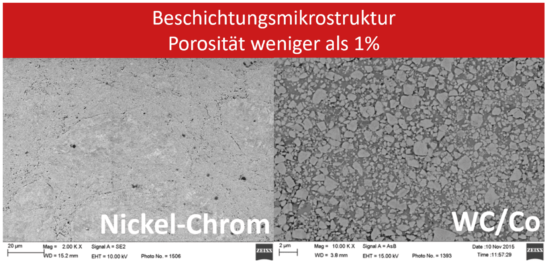
| Porosity | [%] | 3 – 10 | < 2 | 3 – 10 | 2 – 5 | < 1 | < 1 |
| Bond strength | [MPa] | 14 – 21 | 48 – 62 | 28 – 41 | 21 – 34 | 50 – 70 | 70 – 100 |
| Coating thickness range | [mm] | 0.05 – 2.0 | 0.05 – 2.5 | 0.1 – 2.5 | 0.4 – 2.5 | 0.05 – 10 | 0.05 – 0.5 |
| Hardness | [HRC] | < 35 | < 45 | < 40 | < 40 | < 70 | < 70 |
Detonation Spraying
Advantages
Processing of the following materials:
- Metals: copper, nickel, molybdenum, iron and others.
- Alloys: steels, Nichrome, bronze and others.
- Oxides: aluminium oxide, chromium oxide, zirconium oxide, titanium oxide and others.
- Metal-ceramic composites with tungsten, chromium and titanium carbide.
The system technology enables the coating of complex component geometries, including non-standard shapes. The entire coating process is fully computer controlled, ensuring maximum process reliability and quality control.
Working Cycles
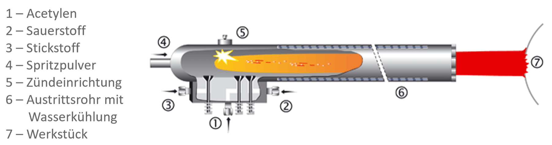
The gas mixture is fed into the gun (1,2,3). The coating material (powder) is introduced into the barrel (4). The gas mixture is ignited (5). The energy of the explosion propels the gas and powder mixture out of the barrel at high velocity (6). On impact with the workpiece, the powder particles fuse with the material surface, forming a coating with a thickness of up to 10 microns (7). The coating thickness is increased according to the number of shots.
Areas of Application
 Aerospace
- Medical technology
- Mechanical engineering
Atmospheric Plasma Spraying
We coat your components.
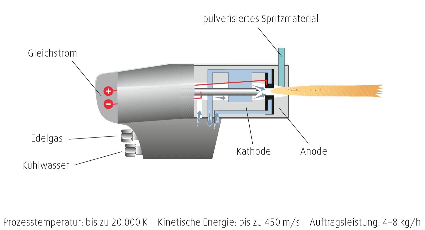
The powder is used as the spray material, melted by a plasma jet and deposited on the workpiece surface. The plasma is generated by an electric arc. The arc burns in various gases and thereby reaches a high outflow velocity, which transfers thermal energy to the spray particles. The arc is non-transferred, meaning it burns inside the spray gun between a centrally positioned electrode (cathode) and the water-cooled spray nozzle, which forms the anode.
You can count on our many years of experience! Do not hesitate to contact us.
Areas of Application
- Aerospace
- Medical technology
High Velocity Oxygen Fuel (HVOF) Spraying
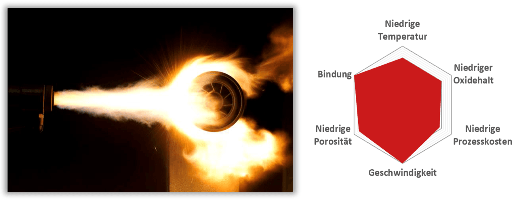
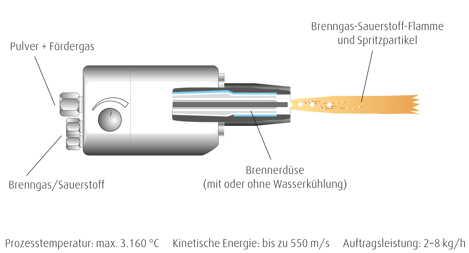
We coat your components. In High Velocity Oxygen Fuel (HVOF) spraying, high pressure is generated by a fuel gas and oxygen mixture inside the combustion chamber, where gas combustion takes place.
The powdered spray material is fed into the central axis of the combustion chamber. Together with the expansion nozzle that usually follows, the pressure produces a high flow velocity in the gas jet. This results in extremely dense sprayed coatings with excellent adhesion properties.
You can count on our many years of experience! Do not hesitate to contact us.
Flame Spraying
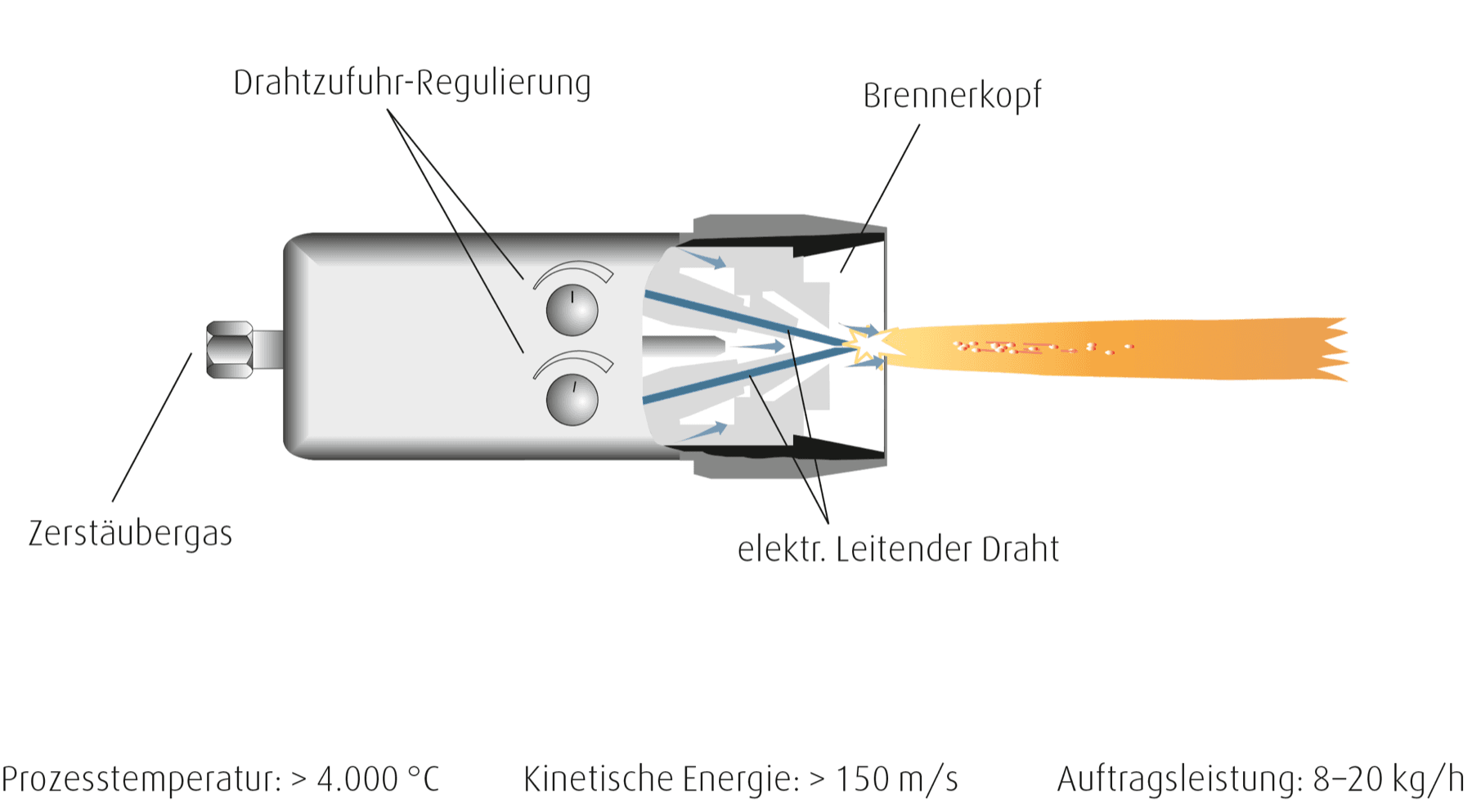
This process deposits wire or powder materials. This achieves longer service lives, and the coating is used for wear protection, corrosion protection and repair. You can count on our many years of experience! Do not hesitate to contact us.
Flame Spraying with Powder
- Important for shaft protection bushings, fans, extruder screw rotors
- The spray material (powder) is melted in an acetylene-oxygen flame
- the resulting combustion gases are applied to the workpiece surface
- A distinction is made between self-fluxing and self-bonding powder
- both are suitable for flame spraying
- self-fluxing powder usually requires subsequent treatment